 Service Literature Development
Par-Tech has provided our customers with outstanding quality and delivery timing for their technical publication needs.
Utilizing highly skilled, automotive experienced service engineers, we have been able to relieve our automotive customers of the burden and internal cost of service literature development so that they can focus on their core business of building cars and trucks.
Areas of Development:
Document Processing and Delivery:
Electrical Troubleshooting Manual:
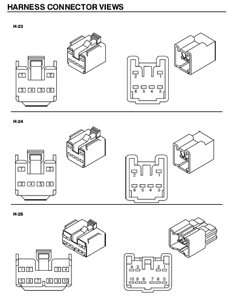
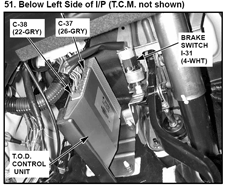
Par-Tech can develop an Electronic Troubleshooting Manual (ETM) for our customer's vehicles. The ETM content is defined as electrical schematics, electrical identification views, schematic legend, connector end views and component location views. Links between the ETM and the service manual will also be provided.
The following is a brief example of the ETM coverage:


Utilizing highly skilled, automotive experienced service engineers, we have been able to relieve our automotive customers of the burden and internal cost of service literature development so that they can focus on their core business of building cars and trucks.
Areas of Development:
- Full vehicle service manual development and validation, including:
- Engine controls
- Engine mechanical
- Schematics development
- Body and accessories repair procedures
- Owners manual development
- Parts catalog development
- Production Assembly Document (PAD) development
- Calibration guideline development
- Service engineering
- Technical illustration
- Document processing
- Printing
- Publishing and hosting on the web
Document Processing and Delivery:
- ESI Development
- Document Processing
Electrical Troubleshooting Manual:
Par-Tech can develop an Electronic Troubleshooting Manual (ETM) for our customer's vehicles. The ETM content is defined as electrical schematics, electrical identification views, schematic legend, connector end views and component location views. Links between the ETM and the service manual will also be provided.
The following is a brief example of the ETM coverage:
- Electrical schematics:
- Power/fusing
- Signal devices (switches, sensors, etc.)
- Controllers (ECM, PCM, relay, etc.)
- Controlled devices (motors, solenoids, etc.)
- Ground points
- Schematic circuit details to include:
- Component boxes: solid box for complete components, dashed box for partial components
- Include internal function or circuit information
- Circuits include circuit number, wire color and wire size
- Connector symbols represent terminal gender in the connector cavity
- Connector identifier is assigned for each connector on components that have two or more connectors (C1, C2, C3, etc.)
- Connector cavity/terminal identification is assigned as it appears on the body of the connector or on harness build prints.
- Switch positions include a description of operation (condition at which the switch is opened or closed)
- Fuse or circuit breakers include voltage indicator boxes for the condition when the device has voltage available to it.
- Schematic illustration is completed in accordance with customer requirements

Click here for an example page from one of our ETMs.
Divided into colorful and easy to read segments, our schematics take technicians from a high level view of the circuit and its components (via hot-spotting) to detailed connector end views and component locations.
Our concept? The easier to see and understand, the easier to diagnose and repair!
Divided into colorful and easy to read segments, our schematics take technicians from a high level view of the circuit and its components (via hot-spotting) to detailed connector end views and component locations.
Our concept? The easier to see and understand, the easier to diagnose and repair!


